
If you wish to monitor and control the temperature of the water, or any other liquid for that matter, this water temperature controller can be of help. It will let you set the maximum temperature to which the water needs to be heated, display the temperature at any stage of the heating process, give indications through a buzzer and LED on reaching the desired temperature, and switch the heater off.

Most storage-type water geysers available in the market for home use have such features, but some water heaters – especially rod-type water heaters – do not provide these facilities. They keep on heating water till they are switched off and thus consume lots of electricity, unnecessarily, and also heat the water much more than desired.
Proof Of Concept Video Tutorial in English:
Proof Of Concept Video Tutorial in Hindi:
Components Required:
| Parts List | |
| Semiconductors: | |
| IC1 | MCT2E optocoupler |
| LED1, LED2 | 5mm LED |
| D1 | 1N4007 rectifier diode |
| Resistors (all 1/4-watt, ±5% carbon): | |
| R1-R3 | 330-ohm |
| R4 | 4.7-kilo-ohm |
| VR1 | 10-kilo-ohm pot |
| Miscellaneous: | |
| BOARD1 | Arduino Nano |
| DIS1 | 4-digit 7-segment display |
| S1, S2 | Push-to-on switch |
| RL1 | 5V, SPDT relay |
| PZ1 | Piezo buzzer |
| CON1, CON2 | 2-pin connector |
| SENSOR1 | DS18B20 sensor |
| Water heater (1000-watt | |
Water Temperature Controller – Block Diagram
The block diagram of this simple project is shown in Fig. 1 and its circuit diagram is in Fig. 2. The project is built around water temperature sensor probe DS18B20, a 4-digit multiplex 7-segment display, Arduino Uno board having microcontroller ATmega328, optocoupler MCT2E, a potentiometer (pot), LEDs, a mini buzzer, and relay.
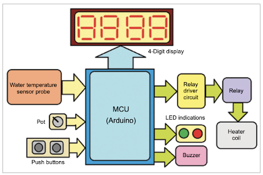
The water temperature sensed by the probe can be seen on the 4-digit display. You can set the required water temperature using the pot and switch on the relay to start heating water. When the water temperature reaches the set level, the relay will automatically turn off and the heating of the water will stop.
The one-wire sensor probe DS18B20 from Dallas recommended for the project senses the water temperature and gives the direct digital value of temperature reading using a special one-wire protocol. Pot VR1 is used to set the required water temperature. DIS1 is a 4-digit multiplex 7-segment display that helps set the required water temperature and know the temperature at any stage. LED1 and LED2 are heaters on/off indicators. The buzzer produces a ‘beep’ sound on reaching the set water temperature. The relay driver circuit (built around MCT2E) provides isolation and protection besides driving the relay.
The 10k pot (VR1) is connected between the 5V and GND pins of the Arduino board with its central slider terminal connected to analog input pin A0. This gives 0 to 5V analog input to the Arduino board. Push-button switches S1 and S2 are connected to pins A1 and A2 such that when a switch is pressed, the corresponding pin is grounded and gives logic 0 input. The two LEDs (red and green) are connected to pins A3 and A4 with their cathodes connected to the ground through 330-ohm current-limiting resistors.
Pin A5 of Arduino Board1 is connected to the anode pin of the LED in optocoupler MCT2E through 330-ohm current limiting resistor R1. The output of the transistor in the optocoupler drives the relay. A reverse freewheeling diode is connected across the relay coil.
Mini buzzer PZ1 is connected to digital pin D0 of the board, with its + input connected to pin D0 and – input connected to the ground. Sensor probe DS18B20 has three interfacing pins marked as +V, OP, and GND. The +V pin is given a 5V supply (external), the GND pin is connected to the circuit’s ground, and the OP pin is connected to digital pin D1 of the board. A 4.7k pull-up resistor is connected between +V and OP pin, as recommended in the datasheet for the DS18B20 sensor.
The 4-digit multiplex 7-segment display is a common-cathode type; its common pin is connected to the ground. Its eight segment inputs (A, B, C, D, E, F, G, DP) are connected to digital pins D2 through D9, and its digit select pins 1 through 4 are connected to digital pins D10 through D13.
Arduino Nano performs almost all the tasks. It reads the temperature value from the DS18B20 probe. Takes user inputs from the pot and switches. Shows water temperature on the display. Gives indications through the LEDs and buzzer. And it switches the heater on and off.
Water Temperature Controller – Working
WHERE IS THE REST OF THIS ARTICLE'S CONTENT?
Related Temperature Controller Projects
Ashutosh M. Bhatt is M.Tech (gold medalist) in embedded systems. Currently, he is a lecturer of electronics and radio engineering at Government Polytechnic, Jamnagar, Gujarat