
The most common cause of fire in a kitchen is gas leakage. This project will help you make an LPG leakage cum smoke detector kitchen security alarm using a gas sensor. The sensor will detect the intensity of LPG gas as well as smoke, if any. If the intensity of LPG gas or smoke exceeds a certain limit, an audible alarm will notify you to take care of the leakage as soon as possible.

LPG/smoke detectors are amazing devices as they are small and low-cost, yet very useful. MQ2 is the most common metal oxide semiconductor (MOS) type of gas sensor. It is very sensitive to smoke and flammable gases like LPG, butane, propane, methane, alcohol, hydrogen, and carbon monoxide. When a gas comes in contact with the sensor, the circuit uses a simple voltage divider network to detect it.
Video Tutorial In English:
Video Tutorial In Tamil:
You can also check the gas leakage detector that we build previously.
The MQ2 sensor has two electrodes made of aluminum oxide (Al2O3) and a heating element made of tin dioxide (SnO2) that acts as the main sensing layer.
| Kitchen Security Alarm Parts List | ||
| Semiconductors: | ||
| IC1 | -LM7805, 5V voltage regulator | |
| IC2 | -LM358 op-amp | |
| IC3 | -NE555 timer | |
| T1, T2 | -2N2219 NPN transitor | |
| BR1 | -1A bridge rectifier | |
| LED1 | -5mm LED | |
| D1 | -1N4007 rectifier diode | |
| Resistors (all 1/4-watt, ±5% carbon): | ||
| R1, R2, R4, R5 | -1-kilo-ohm | |
| R3, R7 | -680-ohm | |
| R6 | -1-mega-ohm | |
| Capacitors: | ||
| C1 | -1000μF, 35V electrolytic | |
| C2 | –1000μF, 16V electrolytic | |
| C3 | -10nF ceramic disk | |
| Miscellaneous: | ||
| Exhaust fan | -230V AC operated | |
| RL1 | -5V, SPDT relay | |
| CON1-CON3 | -2-pin connector | |
| Sensor1 | -MQ2 gas sensor | |
| X1 | -230V AC primary to 9V, 500mA secondary transformer | |
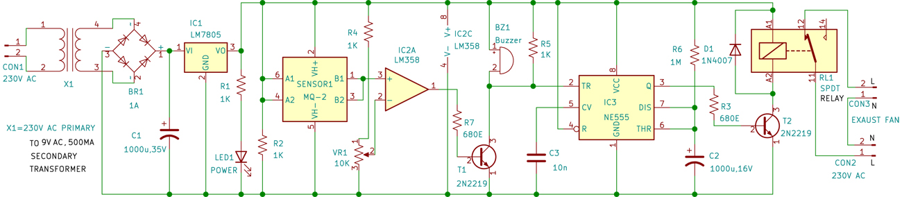
Kitchen Security Alarm – Circuit Connections
The circuit diagram of the alarm using MQ2 sensor is shown in Fig. 1. The circuit is built around step-down transformer X1, bridge rectifier BR1, 5V voltage regulator LM7805 (IC1), MQ2 sensor (Sensor1), op-amp LM358 (IC2), timer NE555 (IC3), 5V SPDT relay RL1, a piezo buzzer (BZ1), and a few other components. Capacitor C1 connected across the supply terminals minimizes voltage ripples and any noise signals.
The circuit needs 5V DC to operate, which is derived from the 9V, 500mA secondary side of transformer X1. The 230V AC mains power supply is connected to the primary of X1 via connector CON1 in the circuit. The 9V AC secondary of X1 is connected to bridge rectifier BR1 for rectification. The rectified voltage filtered by capacitor C1 is given to IC LM7805 to get regulated 5V for the circuit. LED1 indicates the availability of 5V.


Sir,
Thank you very much for the simple, lifesaving, accident and disaster prevention circuit.
Can we use single opamp instead of dual opamp?
Shall we keep the unused opamp inputs floating?
Sir,
Can we use Op-amp Monostable Circuit using LM358 instead of NE555?
Dear Sirs,
please can you correct the link for PCB and Component Layout PDFs?
It seems to be broken.
Hi, the link is corrected.