

Considering the geographical location, some regions experienced temperatures rising to 48ºC during the peak summer season. In such situations, a hydroponic automation system, a water-based artificial farming setup that can be used mostly indoors, becomes essential for growing various crops.
However, a question arises: Is it possible to utilize the water used in hydroponics for an afternoon water shower, scheduling it with the help of the Network Time Protocol (NTP)?
Additionally, can we power the fogger setup to reach all the plants in the hydroponics system?
Here we designed the Artificial Plant Water Showers To Beat The Heat!
At the end of the article, you can check the video to understand how this system works.
The components required to build a hydroponic automation system are listed below.
| Bill of Material | ||
| Components | Amount | Description |
| ESP8266 (MOD1) | 1 | For programming |
| DHT11 (S1) | 1 | To sense atmospheric temperature and humidity |
| DS18B20 (S2) | 1 | To sense the water temperature |
| Peristaltic pump (P1) | 1 | To supply water to the fogger |
| Dual channel relay (MOD 3) | 1 | To control the peristaltic pump |
| Water flow valve (MOD 2) | 1 | To control water flow |
| Misting nozzle (N1) | 1 | To mistify the water for the water shower |
| 6.4mm (¼-inch) barbed connector | 1 | To connect microtubes |
| 6.4mm (¼-inch) microtube | ¾ metre | To connect peristaltic pump with the misting nozzle and water supply |
| Jumper wires (female to female) | 9 | To connect sensors and relay |
Hydroponic Automation System – Block Diagram
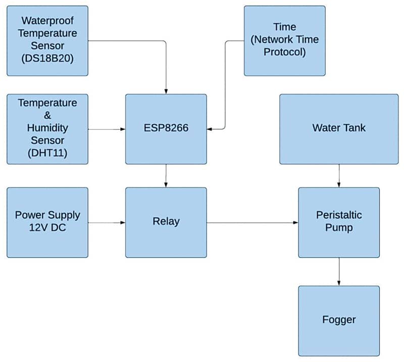
The base setup for this Hydroponic Automation project is located in room D204 of the Institute, with an approximate dimension of 9.3 square meters (100 square feet). The room is non-air-conditioned and does not receive direct sunlight.
The proposed setup aims to test the feasibility of using a 4-way fogger system with the assistance of NTP. We have also implemented on-off controls for the fogger using additional valves and a peristaltic pump for variable flow control.
Fig. 1 presents the block diagram representation of the entire setup.
Fig. 2 showcases the author’s prototype at different stages. The fogger on the left-hand side represents the commercially available product, while the modified set is displayed on the right-hand side.